The pressure of the ship industry gets stronger and stronger. Due to new laws, strict environmental specifications, the high gas prices, the climate change and the decline of biodiversity, the ship industry has to change. The future of many companies depends on new, environmentally friendly technologies. Could fuel cell systems be the key for emission-free shipping? The answer could be given not only by the new study of Germanischer Lloyd, but also by a concrete example: the world’s first fuel cell vessel with space for 100 passengers with the opportunity to adopt the technique to other maritime applications.
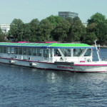
The »Zemships« project was a big success. In summer 2008 the first fuel cell ship that size was christened in[ds_preview] Hamburg/Germany. The »FCS Alsterwasser« has a passenger capacity of 100 people, a length of 25.5 m, a maximal draught of 1.20 m and a height above the waterline of 2.63 m. The roof can be lowered to 2.3 m above waterline. Its propulsion system is completely emission free and allows tourists to ship on the Alster without any noise and vibrations. The propulsion was developed and implemented by Proton Motor. During the first operation of the FCS »Alsterwasser« from 2008 until 2010 two fuel cell systems were implemented, with about 50 kW power each. To use the power efficiently, a hybrid system was used which leads to a combined load of batteries and fuel cells:
When the vessel takes the route on the calm Alster and Alster-channels only one fuel cell system is needed, because the basic load is between 10 and 40 kW. The batteries only support the system at peak loads, as buffer or as propulsion, in case the fuel cell systems break down.
While the project was still running the, the operating company ATG already knew that they wanted to keep the vessel even after the project is over. But on April 28, 2010, an incident happened. During a test drive because of the new stack generation which were implemented, a fire started. There was an uncontrolled heat development on the batteries. Although the ship was on fire the police, the fire department and the Germanischer Lloyd attested that there was not any danger from the fuel cell or hydrogen storage system at any time. The ship is currently rebuilt and the operation starts again at the beginning of the next season.
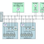
The heart of the propulsion system is the DC-intermediate circuit which supplies all the ship’s electric consumers as well as the auxiliary consumers of the FC-system. The voltage on the intermediate circuit is defined by the batteries.
The batteries are also used as buffer which provide energy for all dynamic processes with short peak loads, as they occur during landing and casting off for instance. Therefore the FC-System only has to provide the basic load and doesn’t need high dynamic load control, which leads to a longer life-time of the fuel cells.
Below the main components of the propulsion system are individually described.
FC-System:
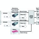
The whole FC-system has three peripherical systems:
1. Hydrogen supply (red inside the scheme)
2. Reaction air supply (green inside the scheme)
3. Cooling (blue inside the scheme)
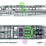
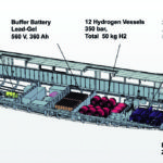
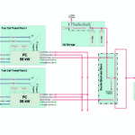
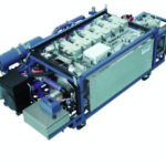
The sectional drawing (Fig. 5) shows the fragmentation of the FC-system as well as all the electrical main components in the hulk. The simplified media scheme (Fig. 6) shows the whole FC-system with both 50 kW FC power packs »PM Basic M50« and the three periphery systems.
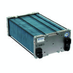
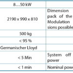
The heart of the FC-system is formed by the two 50 kW power packs »PM Basic M50« which is certified by Germanischer Lloyd as »FC 50«. The »PM Basic M50« produces electricity without any emissions. It is dynamically adjustable and can be integrated in ship applications by dockyards or OEMs without any further amendments because of its closed-system architecture and well-defined interfaces. Furthermore it is possible to use the waste heat by integrating the cooling system of the fuel cell into the passenger heating system to raise the efficiency even more.
Inside the »PM Basic M50« there are six fuel cell stacks of the type »PM 200«, each with 96 fuel cells to get the power required. Furthermore there are the whole peripheral devices and all connections for hydrogen, cooling and air inside the FC power packs.
The modular packaging architecture of »PM Basic M50« allows the simultaneous operation of more fuel cell power packs for power demands higher than 50 kW. If there are two or more power packs operating parallel it is possible to shut down or turn on each system separately in 50 kW steps. Thereby it is possible to fit the power to the particular operation situation. It also allows a redundant power management concept which will lead to an automatic start of the redundant fuel cell systems in case of a system failure on one fuel cell power pack. The FC-control system does the turning on and off automatically.
1. Hydrogen supply
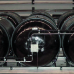
The hydrogen is stored in compressed gas cylinders with 350 bar. The whole hydrogen capacity on board is about 50 kg of hydrogen. Altogether there are four compressed hydrogen storage sub assembly groups, each with three pressure vessels installed inside the hulk. The capacity of one pressure vessel is 4,26 kg hydrogen. Each sub assembly group has a weight of about 290 kg. Therefore the gross weight of all compressed gas cylinders with filling is about 1,16 t. The stored hydrogen allows an operation of three days without refilling. The hydrogen vessels are in a segregated area in the hulk which is declared as Ex Zone.
For the operation hydrogen 5.0 is needed. In two pressure stages the hydrogen pressure is reduced to 400 mbar, which is the working pressure of the fuel cells. The first pressure stage, which is also in the Ex Zone, reduces the pressure to 6 bar. The second pressure stage triggers the working pressure of the fuel cell.
2. Reaction air supply
The air needed for operation is delivered by a compressor which is integrated in the »PM Basic M50«. This compressor takes the ambient air out of the hulk, takes it over an integrated air filter and takes the reaction air to the fuel cell under working pressure of 600 mbar, where the chemical reaction of hydrogen and oxygen takes place.
2H2 + O2 —> 2H2O
The waste air and the contained residual moisture are carried to the outside via pipes.
3. Cooling
The fuel cells inside the PM 200 are liquid-cooled fuel cells and so a dual circuit cooling system was installed. The primary cooling circuit is inside the fuel cell power pack. It is cooled by a mixture of water and special glycol. The separation to the secondary cooling circuit is done by plate heat exchanger which is also inside the packs. The waste heat of the fuel cell is used for the heating system on the ship; the heat which cannot be used is led over a heat exchanger on the vessel’s side.
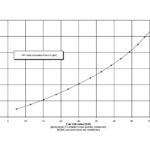
The fuel cell has different degrees of efficiency which depend on the power. The chart in Fig. 9 shows the heat development in dependency on the power.
The controlling system
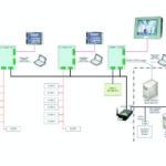
Both »PM Basic M50« FC power packs have separate control systems. Furthermore there is an installed master control which coordinates both FC power packs as well as the communication with the hydrogen storage system and the ship. The master control also allows the visualisation for the passengers and the captain.
Inside the FC control of each power pack every single cell of the 576 fuel cells is monitored by the »CVMU« (Cell Voltage Monitoring Unit) to intervene in case of an voltage drop.
Over the master control the relevant operating dates are saved on a data logger. In case of incidents the data can be called up over remote enquiry and analysed to identify the problem and find a solution at the office of PM which leads to significant savings in time and costs.
Battery buffer
Since the FC power pack in operation delivers unregulated DC-voltage of 360– 660 VDC, a DC/DC-converter adapts the fuel cells to the batteries. The batteries of the »FCS Alsterwasser« are lead-gel batteries, which are licensed by Germanischer Lloyd. Altogether there are seven battery boxes installed on the ship, each with 80 V. In one battery box there are 40 cells with a voltage of 2 V and 360 Ah. The weight of the batteries is about 7 t including the battery container.
Due to the fact that the fuel cells are recharging the battery during the operation, the batteries have a constant state of charge level. If the vessel is moored at the pier, the batteries are charged from outside.
Because of the prototype character of the »Alsterwasser« such a high battery capacity was installed to insure that in case of a fuel cell break down the vessel can reach the pier only with the power of the batteries. As the operational experience has shown the battery capacity can be lowered.
Power management
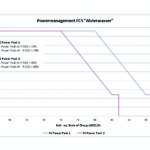
To regulate the power output of the propulsion system there is no need for an interface to the ship because the whole power is taken out from the batteries. How much power the fuel cells deliver depends on the state of charge (SOC) of the batteries. In Fig. 12 there is the power management exemplified.
At the SOC of 95 % the first FC power pack starts with the minimum power of about 8 kW. When the power requirement of the ship is increasing energy is taken from the batteries which causes a decline of the SOC. The result is that the fuel cell system has to put in more electric energy to the batteries. That raises the FC-power. At a SOC of less than 80 % the second FC power pack starts with the minumum power of about 8 kW.
Example:
SOC 80 %
FC power pack 1: Pel = 48 kW = Pmax
FC power pack 2: Pel = 23 kW
Pges = 71 kW
If the fuel cell power produces a higher SOC the second FC power pack stops as soon as the SOC is above 85 %. The FC power pack stops as soon as the SOC is again over 97 % to prevent overload.
Hydrogen and Safety
Hydrogen is a transparent, odourless, completely non-toxic gas which is lighter than air. Due to its physical and chemical characteristics there are no abnormal risks.
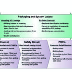
To guarantee a safe installation and operation of fuel cell systems for marine applications the safety concept of the fuel cell propulsion system of the »Alsterwasser« is set up in four different categories.
First category – packaging and system layout
Primarily, the system is designed and mounted to avoid leakages. Secondly, the system is divided into different, self-containing sub assemblies which are installed into different sections of the ship according to their risk assessment. Assemblies with a higher possibility of gas leakage, e. g. hydrogen high pressure system, are installed into sections defined as »Ex-Zones«. Assemblies without any risk as the PM Basic 50 are installed into Ex-Zone free sections.
Furthermore gas pressure pipes get either depressurised or made inert by means of nitrogen if they are not required for the operation of the FC-system. All low-pressure pipes are made inert with nitrogen if they are not in use. For this purpose t removable gas bottles of nitrogen are stored on board. The high-pressure and medium-pressure pipes will be depressurised by a valve combination (double block and bleed) and separated from the hydrogen tanks by normally closed valves.
Second category – control
The fuel cell system is controlled by a microcontroller and a so-called Cell Voltage Monitoring Unit (CVMU) which will keep the fuel cell system in a normal operation condition.
If the normal operational conditions are exceeded, for example by excess temperature or overpressure, the software will normally shut down the system to prevent it from being damaged and hydrogen from escaping.
Third category – safety circuit
The fuel cell system is also equipped with a hard wired safety circuit which will trigger an emergency shut-down for either the complete fuel cell system or part of the system. The switching points for excess temperature, overpressure or less flow are physically placed »after« the software. The safety circuit prevents the system from getting damaged and prevents hydrogen from escaping to the surroundings.
Fourth category – pressure relief devices
The last category in the safety architecture of the fuel cell system are pressure relief devices, like safety valves or melting fuses. These devices are the last in line and will release the hydrogen contained inside the system in a controlled manner in case of a serious incident in order to prevent serious damage to man and machine.
Fuel cell types and application areas
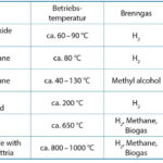
A fuel cell is not an energy carrier, but an energy converter. The fuel cell modifies chemical in electrical energy and has an electrical efficiency of 35 %–70 %. There are different fuel cell types which suit for several applications. The difference is caused by the core of the fuel cell, the electrolyte. The electrolyte determines the fuel and the operating conditions, for instance the working temperature, the appropriate cell types and therefore also the configuration of the stacks (see table below).
Proton Motor decided to use the PEMFC, because this type is the best for the markets focused on by PM.
Operating mode of a PEM (Proton Exchange Membrane) fuel cell
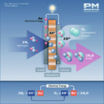
Oxygen (O2) and Hydrogen (H2) produce energy inside the fuel cell stacks. On the one hand in form of electricity and on the other hand in form of heat. The required hydrogen can be provided in liquid, gas or over a reformate.
The chemical reaction: On the anode the hydrogen is split into electrons and protons (donation of electrons):
2H2 —> 4H+ + 4e–
The protons reach the cathode via the polymer membrane, whereas the electrons reach the cathode via a conductor. Thereby electricity is generated (DC). On the cathode the protons accepting the electrons again:
O2 + 4H+ + 4e —> 4H2O
For fuel cell applications the energy is not delivered by a single fuel cell, there always has to be a fuel cell stack. In case of the fuel cell stack »PM 200« 96 cells provide the total energy. The stack needs hydrogen and oxygen and gets cooled by liquid. A stack is a multitude of many single fuel cells. The chemical reaction occurs in each single cell. The power of the stack is therefore defined by the number of cells installed. The maximum number of cells is defined by 96 cells. For power demands which exceed the power capability of one stack, a series connection of more stacks is required to allow the production of sufficient energy. The fuel cell as zero emission solution could be the first step into the right direction. Proton Motor already offers standardised and ready for assembly systems.
»PM 600«, the predecessor of the »PM 200« – basic differences
The »PM 600« is the stack generation, which was first installed into the »FCS Alsterwasser«. Presumably at the beginning of the next year, the »FCS Alsterwasser« is taken back into operation with the new stack »PM 200«. The basic difference is in the durability, which is extended by the factor 10–15 as well as the performance of the stacks. Compared with the new generation the PM 600 only has 48 cells but also an current output of 350 A. Furthermore the maintenance is better because the cells of the PM 200 can easily be changed without changing the whole stack, which leads to an enormous cost benefit. The membrane and the used platinum can be better recycled.
Further possibilities for using fuel cells in vessels
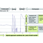
The enormous performance requirement of vessels which need over 1,000 kW can not be provided by fuel cells only. Nowadays it is tested if a fuel cell system can produce enough energy for such huge vessels to provide the necessary electricity on board. Today, vessels get their board energy supply from ordinary diesel engines These are not only inefficient but also produce a lot of emissions, mainly in harbours. By the use of fuel cells it would be possible to turn off the main power plants and get the electricity from fuel cells which are responsible for the board energy needed. Furthermore it is possible to use a fuel cell system as a secondary engine in operational modes with little power demand. Because of the bad efficiency of diesel engines, mainly if less power is required, a hybrid system with an intelligent power management concept between the diesel and the fuel cell system could lead to economic system setups with less exhaust and higher efficiencies.
Another possibility is to use them as auxiliary power units (APUs). Because of their modularity it is possible to locate them decentralised and to provide the energy at places where electricity is needed, for example as uninterruptible power supply systems (UPS) or emergency-power supply, without any cabling or piping that have to run through the complete ship. For the need of UPS or emergency-power supply systems Proton Motor can supply a standardized, modular fuel cell powered UPS in 19« rack set up.
Proton Motor fuel cell GmbH
Proton Motor (PM) is a specialist for industrial fuel cells and hybrid systems, with the registered office in Puchheim/Munich. PM has more than 15 years of experience and know how in development and production of fuel cells and fuel cell systems, up to the implementation of customised turnkey solutions. The first concepts for maritime applications started in co-operation with »HDW Fuel Cell Systems« in 2004. After ThyssenKrupp Marine Systems took over, HDW stopped all activities around fuel cells for civil applications. Thereupon PM took the initiative together with the »Brennstoffzellen- und Wasserstofftechnologie Hamburg« for concrete project ideas to implement in 2005. With the development of »PM Basic M50« Proton Motor set a standard in maritime applications. The fuel cell system is ready to be installed and with the new stack generation »PM200« from Proton Motor a realistic solution to reduce emissions in the navigation.
The fuel cell system proved its liability, at least in the canal shipping and the tourist cruise business. Technological advancements are being pushed, the shipping industry has to reduce the emissions. If fuel cells contributing for a more efficient, less emission shipping, will be shown in the future.
Dipl.-Ing. Manfred Limbrunner


